Sunday, 20 March 2016

Quick and not so dirty

Quick and Dirty

When I first approached this design I took the section lines of the skiff,

and simply rounded the chine corners. Then I adjusted the rounding so that the curves were parallel. I also narrowed the pram bow at the waterline to give a finer entry


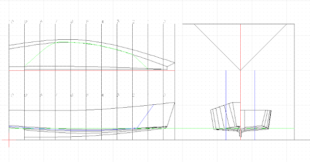
I then went through the process of waterlines, buttocks and diagonals to get this,


Compare that to this, which is the hull we've developed over the past few weeks

 Here's a comparison of the sections side by side, the red being the lines developed from the skiff by rounding and the black being our skiff, and also superimposed.

On the face of it I can't see much difference and it was very much quicker. Our skiff is a little finer in the bows and the Q&D version has a bit more displacement, that's about it.

Now that that is done I will run some numbers on the two versions to see what difference, if any, there is.

Numbers

BY THE NUMBERS

I ran the numbers on these two versions, here they are,

Version
RMSQ&D
RMS
Displacement
304.89 lbs
266 lbs
Block Coefficient
0.18
0.16
Prismatic Coefficient
0.48
0.53
Area of the waterplane
25.55 sqft
27.78 sqft
Centre of flotation (aft or forward of Station 5)
.4381 ft aft
.4772 ft Aft
Lbs per inch immersion
152.29 lbs
137.49 lbs

So what does that mean exactly?

Well Q&D can carry more weight at the designed waterline by about 40 lbs and it takes more weight to sink it any further into the water.

Skene's sets out that a prismatic coefficient between .49 and .55 is best for sailing vessels, any more than .55 and you have a tub, any less than .49 the vessels is so fine it drags a huge quarter wave. So Q&D is on the fine side and RMS is within the parameters set out by Skene's. However the block coefficient tells us another story, by that coefficient RMS is the finer vessel.

Skene's also sets out that the center of flotation should be between 54 – 59% of the LWL aft of station 0 or in our case, between .48 ft aft of station 5 to 1 ft aft. So Q&D is a bit too far forward and RMS is just about right.

The LWL is 12ft for both these vessels and the beam at the WL is 5ft 4in which is a beam to length ratio of 2.5 which is a little beamy, anything from 3 to 5 is better, but the beamyness in such a small vessel adds to the initial stability.

Next time we'll look at stability.

Friday, 4 March 2016

On the Fiddle

The Fiddly Bits

Adjusting each of the lines so that they are fair takes a fair bit of time because they have to be fair in all three views. With pencil and paper this takes more hours than you can count as you try a new curve and erase the old one only to find that some other line is not fair because of the change you made.

This takes much less time on the computer. Each curve has nodes where they intersect with other lines,

The blue squares are the nodes. Each of these nodes can be moved to adjust the curve. I use this little gadget to determine how far to move the node.


The concentric circles are 1/8th inch apart and at the centre is a reference point. I put the reference point on the curve I want to adjust,


and move the node an 1/8th inch at a time until the curve looks right.


Then of course you have to transfer the new intersection to the other views and adjust those curves. After about a half hour of fiddling I got to this.


The lines are all fair to one another and the flow aft is smooth. In the next post I will show you another set of lines for this same boat which took only two hours to do from start to finish and I'll tell you how I did it.


Sunday, 28 February 2016

Buttocks - not that kind!

Buttocks

Buttocks are also fairing lines and show the flow of water around the hull. Usually two buttock lines are used and are shown only on the profile as they will be straight lines in plan. They are drawn first on the sections, the blue lines,


and then the intersections transferred to the profile and then joined by curves.


You can see that we have the same hump at station 1 as we had in the diagonal. The flow aft appears good, perhaps we should have a third buttock line to better define that flow.


That third buttock shows a definite problem aft of station 5. This where the fiddly bits come in, adjusting all the lines so that they are fair to one another

Saturday, 20 February 2016

Somewhat askew

Diagonals

Diagonals are fairing lines that help develop the shape of your boat so that it presents less of an obstacle to smooth movement through the water. Most designers will tell you that diagonals are shown on the plan view on the opposite side from the water lines. I prefer to simply use a different colour, in this case magenta. They will also tell you that diagonals are not shown on the profile. I prefer to show the diagonal as it helps me “see” the hull.

Diagonals usually go from some defined point on the centreline to the turn of the bilge, there may be more than one diagonal in a larger vessel in which case they are not numbered but identified by letters. In our case only one diagonal is needed.

The intersections are then transferred to the plan and profile using the method we have already discussed here.

The transferred intersections are then joined to form curves.

First in plan,


and then in profile.

These look very smooth and fair but if you look closely at the intersection with station1 in profile you can see a definite hump in profile and hollow in plan.


We'll put the buttocks in first before attempting any corrective action.


Monday, 15 February 2016

Sections Redux


Sections yet again

In the last post we had drawn in the waterlines in plan now we can go back and construct the sections in the same way as we did here. The thing is here there are more intersections and instead of joining them with straight lines we join them with curves.


In the first iteration the sections look like this,


So we'll go with that as it looks good. You'll notice that I said the first iteration but now comes the tricky bit, buttocks and diagonals.

Tuesday, 19 January 2016

The Thin Green Line

The Thin Green Line

In my last post I said that I would explain the use of the multiple waterlines. Firstly, why are they green? Because I like them green, as soon as I see a green line I know it's a waterline.

Why are there so many? Because we will use them to develop the 3D shape of our boat along with other reference lines.

So far we have our midsection, bow transom and stern transom. The thing that joins these entities is the water line, By transferring the location of the LWL on these three sections we can start to develop the shape.

First we draw in several waterlines. I will explain further later.


Next we locate the point of contact in plan of the LWL and the three sections thusly, note the red circles,

and join the points with a fair curve, very easy on the computer.


Then we do the very same thing for each of the other waterlines like this,

Until we have this,

You can deduce from what we have just done the reason for the many waterlines.

Now we can go back and construct the other sections using the waterlines we have just created.