Monday 25 April 2016

Stability

Next to last kick at the stability cat

Well it turns out that it does work for small round bottom boats and boats without two parallel sides. I wouldn't say that it is one hundred per cent accurate but for the boats we're dealing with it's close enough. Here's how we go about it .

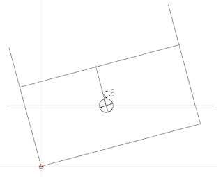
This is the hull we dealt with last time,


So I took that hull shape and rounded off the corners, gives a sort of canoe shape,

We'll keep the centre of gravity the same but the waterline needs adjusting to account for the change in underwater shape. Once that is done then we're going to create a trapezoid, first by cutting off the round parts, those volumes are so small, and equal in area, 50 sq inches, that it makes little difference to the calculation at this juncture.


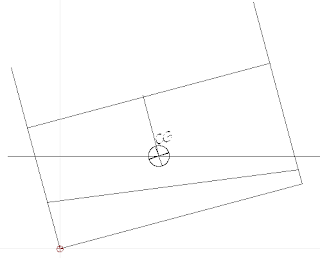
Now we're going to join the upper ends of those lines that cut off the round part to make a trapezoid and a triangle and then find the centre of those bodies as we did previously.


Once we have both centres then we need to do some calculation, first we'll join both centres with a line. Our centre of buoyancy is somewhere on that line. But where.


In my last post I sent you to Jim Michalak's page here, http://www.jimsboats.com/1dec15.htm where he sets out how to calculate the center of effort of sails. We can do the same thing here. So lets name the triangle area small or AS and the trapezoid AL. We'll call the line joining the two centres LS-LL. Now we measure the area of AS and AL and the length of LS-LL
AS is 131.45 sqin and AL is 270.75 sqin, LS-LL is 12”. Divide AS into AL and add 1, that come out to 3.06. Divide LS-LL by 3.06, which is 3.9. The center of buoyancy is 3.9 inches from LL.

I can hear the mathematicians out there saying that's not right! But here's an example using a lever and fulcrum.
How much weight do we have to hang off the end of the nine foot arm to balance the lever assuming the lever weighs nothing? (which is what we're actually doing when we calculate the relative distance of the centres of our areas)

10x3/9 = 3.33 lbs

So now lets turn that around and say where do we put the fulcrum to balance a 10 lb weight and a 3.33 lb weight on a 12 foot lever?

((10/3.33)+1) divided into 12' = 3' from the heavy end.

Getting back to our vessel, at 5 degrees of heel the righting arm is 2.5” and GM is 2' 4.8”


How does that compare with our square bottom vessel? At the same degree of heel the square boat had a righting arm of 1” and a GM of a foot however if you overlay the two at the waterline,the centres of buoyancy are almost identical.


Next time a quick look at a greater degree of heel and a rounder bottom vessel and one without parallel sides.

Wednesday 6 April 2016

Stability Again

The stable Farmer

In his book, My Old Boat Shop,WestonFarmer observed that he had discovered a rule of thumb target for comfort at sea and that was the pounds per square foot loading of the waterplane. He surmised that the optimum loading was 64 pounds per square foot of the waterplane, or to put it another way the underwater volume should be the area of the waterplane times 1 foot. He theorized that this would make the vessel the same weight as the sea surrounding it and thus the vessel would move with the sea not out of sync with it as would a lighter or heavier vessel. But what about the stability of such a vessel?

This idea intrigued me so I did some follow up. To dissect this theory we'll use a closed box 10' long by 4' wide and 2' deep. In the first iteration the box weighs 64 lbs per cubic foot or 128lbs per sqft of waterplane.


The green line is the waterline, the centre of gravity and the centre of buoyancy coincide. Logic tells you that this arrangement would not be very stable as it would rotate about the centres completely underwater. Add some sides,

Stability increases but comfort doesn't as the boat would move out of sync with the movement of the water. A wave passing through would start the boat moving upwards but not at the speed of the wave. As the wave passed and the trough arrived the boat would continue upwards due to inertia and then start to fall as the next wave arrived creating a very uncomfortable motion.

So what would happen if we loaded the boat as Mr. Farmer suggests?

Here it is,

Mr. Farmer's theory is that this loading would be very comfortable as the boat would move in sync with the water, Stability is much improved as the centre of bouyancy is now below the center of gravity and would move outboard as the boat heeled. Let's take a look at how that would work.

Here is our box boat at 40 degrees of heel,

However the immersed volume is too great so we must adjust the waterline (WL) and then determine the center of buoyancy, which is a piece of cake with a triangle.


You all remember your basic geometry of course. From that we can determine the metacentric height for that angle of heel and the righting arm.


But what did I discover? Here it is - If you look at the diagram above where we found the center of the triangle you'll notice that the line from the top left to the middle of the right side cuts though the deck line exactly in the centre, from that we can deduce that the center of buoyancy falls on a line joining the mid points of the two parallel sides. But where on that line?

Jim Michalak in a post here,  http://www.jimsboats.com/1dec15.htm shows you how to find the centre of effort of a four sided sail, that same method can be used with the above knowledge to find the center of buoyancy of a four sided immersed section but without the math. Here we go.

Here's our boat at 15 degrees of heel, the immersed volume is four sided.


First we join the two mid points,


Then divide the four sided figure into two triangles, find the centre of each and join the two centres.


Where the two lines joining centres and midpoints cross is the center of buoyancy.


But will it work for boats that don't have two parallel sides or a round bottom boats. Next time.

Saturday 2 April 2016

Stability One

Staying upright or at least afloat

Here's the real deal on stability in small boats, modern sail boat design http://www.wavetrain.net/boats-a-gear/471-modern-sailboat-design-quantifying-stability. Which is perfect for larger boats with decks and a mostly fixed centre of gravity. But what about small open boats such as the one we've just been working on. Well here is the stability curve for RMSQ&D assuming a fixed centre of gravity.


So degrees of heel are on the X axis and righting arm, in inches, on the y axis. The reason we've only gone to 45 degrees is because beyond that water is coming in over the gunwale and you're going down.

You can see that this boat has a pretty good level of stability up to 45 degrees which is great. However the fact is that you, the person in the boat, has a huge influence on the stability through your ability to move the centre of gravity by moving yourself about.

The question is how did I calculate the data for this curve? It is mind numbing work involving drawing and redrawing waterlines at various degrees of heel and then calculating the centre of buoyancy using stations and Simpson's rule. It is not for the faint of heart. Information on the process is here, www.mi.mun.ca/media/mi/boatrace/files/shipcalculations2.pdf , and here, http://koti.kapsi.fi/hvartial/stab/stab.htm.

The one thing to remember is when you draw in the new waterline at a different angle of heel the displacement must remain the same. With the boat dead level the displacement of station 5 is 109.118 cubic inches, or .7578 cu ft or 48 lbs However when you heel the boat 10 degrees without altering the waterline the displacement is 136.706 cu in, or .9493 cu ft. So we must reduce that displacement by .1915 cu ft, so the waterline must go down but by how much?

If we measure the new waterline it is 3.4 ft, 3.4 into .1915 is .056 ft or .675 inches so we draw in the new waterline .675 inches below the old water line and measure the difference in volume which works out to 28.642 cu in which brings our displaced volume down to 108.064 which is close enough.

We then divide the new waterline into 10 sections, making sure one station line passes through the centre of gravity, giving us the measures for applying Simpsons rule and calculate the transverse centre of bouyancy for station 5.

And then we do it all again for different angles of heel.

Westlawn recommends using the trapezoidal rule instead of Simpson's I don't think there is much difference in the end result.

The thing to remember is that beam is directly proportional to initial stability. But too much beam can create problems with dynamic stability.

We'll talk more about stability next time and about a discovery I have made whilst working on this.